|
|
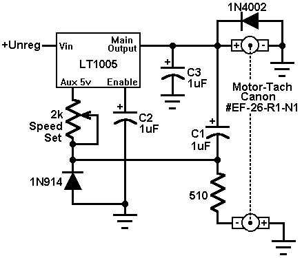
This circuit uses an LT1005 regulator to form a switched mode motor speed controller. This circuit uses a tachometer to generate a feedback signal which is compared to a reference supplied by the auxiliary output. When power is applied, the tachometer output is zero and the regulator output comes on, forcing current into the motor. As motor rotation increases, the negative tachometer output pulls the ENABLE pin toward ground. When the enable pin's threshold voltage is reached, the regulator output goes down and the motor slows. C1 provides positive feedback, ensuring clean transitions. In this fashion, the motor's speed is servo-controlled at a point determined by the 2k potentiometer setting. The regulator free-runs at whatever frequency and duty cycle are required to maintain the ENABLE pin at its threshold. Loop bandwidth and stability are set by C2 and C3. The 1N914 diode prevents the negative output tachometer from pulling the ENABLE pin below ground while the 1N4002 commutates the motor's negative flyback pulse. The servo-controlled pulse mode excitation allows the motor to furnish excellent torque characteristics, even when operating at 5% of its full speed rating. For example, the small motor shown, with a shaft torque rating of 20 gram-cMs at 3300RPM, is almost unstoppable by the unaided human hand at 150RPM. The thermal and current limiting in the regulator prevents either the motor or the regulator from burning up in the event of a shaft overload.
|
|